Forum sponsored by:

General

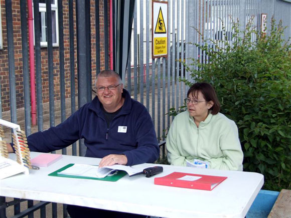
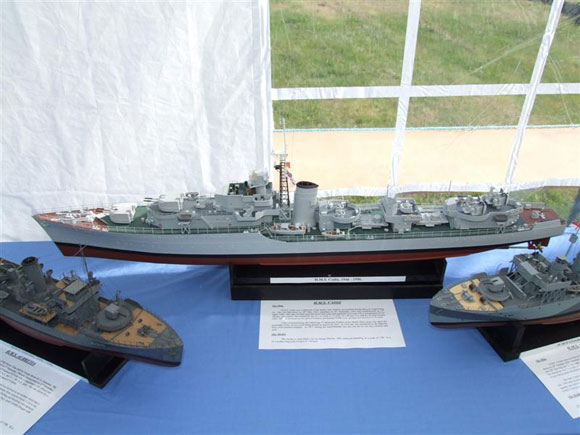
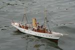
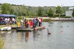
Welcome again! This month we visit the Merstham Model Steam event, the Alford Charity show and continue the modification to electric power of the Billings Karoline, otherwise known as the potato boat! The Merstham Model Steam ShowThis event at St. Nicholas School in Surrey has been running since 1985, but this was the first time we had an opportunity to pay it a visit. Directions to the school, plus information about the event, are on their website at www.mmss.co.uk. The event takes place in the grounds of the school, the majority of the exhibitors located either in large marquees or in their own individual gazebos or caravans with awnings. The school opens up the main hall and gymnasium as well for the exhibitors and traders. In addition there is a large outside swimming pool on which models can be sailed. The core of the show are model steam railways. The school has its own 7 1/4ins gauge passenger railway in the grounds and naturally most of the exhibitions and traders are model railway enthusiasts. However, with an outside swimming pool, there is a good representation of model boats with a few familiar traders present. The model boat activity on the outside swimming pool was in the capable hands of Alan Colson, who is also the principal organiser of the Alfold charity model boat show, Photo 1. The lady with him? That is Marion, my ever supportive wife. The models are displayed on tables around the edge of the pool and there was a good cross section of model types on display. Photo 2 is of a small steam launch, nicely made with a simple V twin oscillator, Photo 3, which looked like one of Peter Arnot’s designs. During the day the pool attracted an enthusiastic audience, Photo 4. In the grounds were several model boat clubs. Dennis Freeman had his model fishing boat on display on the Chantry club stand, Photo 5. Not far away were the model boat traders, George Turner Models, Hunter Systems, Wiltshire Models and Modelpower Supplies. Tools etc. were available from the Tools 2000 stand. Modelpower had some new bits and pieces. The first were these bullet connectors, Photo 6, normally used by the fast electric modellers, but equally useful if you require a connecter to handle a high current. These 4mm gold connecters can handle up to 80 amps. These were £7.95 for ten, with the plastic housing. The other new item was this universal charger, the RC Power 601 BC. This was a truly versatile charger, capable of charging NiCads, NiMH, SLA plus the new Lithium Ion and Lithium Polymer cells that are becoming increasingly popular. The unit is also capable of ‘balancing’ these types of batteries, Photo 7. The Merstham show is a very pleasant laid back type of show and the entry fees help to provide recreational facilities for the pupils who have learning and behaviour difficulties. The show is usually held on the third weekend in May. Alfold – 11th Charity Model Boat ShowA couple of weeks after the Merstham show saw us at the 11th Charity Model Boat Show at Alfold. Set in the grounds of the Springbok Estate, this model boat show consists of club and trade stands with food, drink and bring and buy stalls. Sailing takes place on the lake adjacent to the displays. Caravan and camping is permitted if booked in advance and there is a barbeque on the Saturday evening. The Merchant Seamans Home also has a bar. Clubs and traders travel from near and far to the show. We spoke to Bob Iles from Pembrokeshire who was exhibiting a range of model warships based on the Deans Marine range, plus his Mountfleet Models St. Nectan trawler. Photo 8 is of Bob’s model of HMS Cadiz, a Battle class destroyer, commissioned in 1946. |
|
This model is framed by two corvettes, HMS Aubrietia to the left and HMS Crocus to the right. The pennant number of HMS Crocus was used on the fictional ship HMS Compass Rose in the film ‘The Cruel Sea’. Photo 9 is of Bob’s fine model of the St, Nectan. At 1/32 scale, the model is 68ins long with a beam of 11 1/2ins. Sailing weight is 66 1/2lbs. The model has working navigation lights and deck floodlights. The radar scanner rotates and it also has siren and steam engine sounds. John Melville had a couple of models he was putting into the ‘Bring and Buy’ sale. This model was unusual not only in looks, but that it also comes from the 1950’s. This is the M.S. Northern Star. This model, unpowered, was offered with the original building instructions and construction diagrams, Photo 10. John was also selling this steam launch, Photo 11, complete with a twin cylinder Saito steam engine, Photo 12. This very nicely executed model of a small launch was built by Paul South and based on a free plan ‘Bobby’ from a 1970’s Model Boats magazine, Photo 13. The model is driven by a Monoperm Superspecial motor powered from a 6v NiCad pack and uses a home built speed controller. Terry Moffat from the Southend Club had his model of a Bristol Channel Pilot Cutter on display. This was based on a 1:20th scale David Alderton hull and used his rigging blocks as well, Photo 14. Dave Vaul from the Hanwell and District Model Society had his Flintstone Raft Yabadabado on the stand, Photo 15. Barney Rubble, at the stern, seemed to be the only one doing any work! David Heaps had brought his model of the Clyde car ferry Bute still under construction, Photo 16. Scratch built using a ply frame, in-filled with foam and covered with a fibreglass skin, the model has twin screws operated independently. The car lift is also operational, the same as the original. David’s notes explain that this system allowed cars to be driven on board from the pier. When a number had been loaded, the lift took them to the upper or lower deck where they were rotated through 90º and driven to their parking place. The lift not only allowed the use of two decks but also compensated for the level of the tide at the pier. The Bute was launched in 1954 and was used well into the 1980’s. As usual there was plenty of activity taking place on the lake – Club 500 racing and scale sail in addition to the normal scale model activity. Photo 17 shows Graham Fright of the Southend Club controlling the start of the Club 500 race. The last time we saw this cracking model of the Waverley it was at Brighton Modelworld Show, Photo 18. Built by Peter Watts, the model is to a scale of 1/48. It is built from 1mm ply on balsa wood frames and uses an electric motor through a 28:1 reduction gearbox to power the paddle wheels. It was good to see an increase in trade presence this year which helps to make the show a success. We understand from Alan that the show raised in excess of £2500, which will go to the Merchant Seaman’s War Memorial Society and two other charities. I was thankful that the weather kept up its record of being warm and sunny all weekend and look forward to next year when the show will take place on the weekend of May 31st/June 1st. Alford ResultsBest in Show |
|
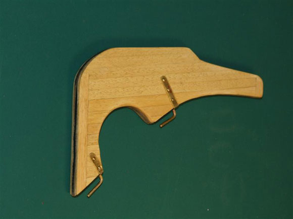
Karoline Modifications - Part TwoThis is a Billings kit of a sailing vessel, otherwise known as the ‘Potato Boat’ which I am converting to also have the facility of motor propulsion. So, continuing from last month, the pintles were fitted to the rudder, Photo 19, formed to shape, drilled and pinned. The rudder was also given a couple of coats of sanding sealer at this time. With the rudder put to one side, it was time to consider the installation of the drive motor and shaft assembly. Before this could commence, it was necessary to remove the sail winch, rudder servo and radio, Photo 20. Once the mechanics were out of the way, the wooden mounting plates were sawn in half and gently eased from their mounts and then disposed of. With the hull inverted, a batten was taped to the keel to give a datum from which to work. Photo 21 shows this in place with the position of the shaft exit hole marked and in the process of being drilled out. The drill only looks as if it is angled due to the lack of support while the photo was taken – it was in fact parallel to the keel. I had in stock a suitable propshaft assembly, so all I had to do was fit an oiling tube to it. Photo 22 shows this process. The oil tube was glued into position using epoxy adhesive (Araldite). With the hole in the keel for the propshaft suitably enlarged the tube was fitted and checked for alignment. The technique I usually use is to fit a long rod of the correct diameter into the tube and use this to visually align the tube to the hull. In Photo 23 you can see the long brass rod in place and its position relative to the keel. When satisfied that the tube is aligned correctly in all planes, I tacked it in place with Superglue. If a mistake is subsequently noticed, it is relatively easy to break this joint and begin again. As everything was ok I glued the tube with epoxy adhesive. As the inboard end of the tube is a little away from the stern, I made up a wooden support for it. This goes over the end of the tube and locates in the bottom of the hull, Photo 24. I next prepared a suitable drive motor. I had in stock a spare 555 motor from Model Motors Direct. Photo 25 shows the motor suitably suppressed (I get my suppressors from ‘Action’, but they are available from most good model suppliers) and a wiring harness complete with a Tamiya plug for connection to the speed controller. Moving forward a bit, Photo 26 shows the motor held temporarily on its mount which has been shaped to suit the profile of the hull. The motor is held with an elastic band, but it will be embedded in a bed of kitchen/bathroom silicone sealant. The rudder servo is also shown fitted onto its mounting rails which have also been prepared to suit the profile of the hull. Photo 27 has the motor, coupling, propshaft and rudder servo in place. Close inspection will show that the wooden motor mount has been glued with epoxy adhesive to the hull, as have the servo mounting rails. The motor has been positioned temporarily to add weight to the motor mount while the glue dries. A suitable propeller from stock, a used 40mm with four blades, has been fitted to the propshaft, Photo 28. This was tried earlier to ensure sufficient clearance from the hull. A new tiller arm was fabricated from 1.5mm brass rod and a wooden bead (from wife’s stock!) glued to the end. This was fitted to the rudder as well as two right-angled, pre-drilled brass plates to take the rudder linkage. One of these can just be seen between the tiller and the upper rudder pintles, Photo 29. I had in mind to use a push-pull arrangement between the rudder servo and the rudder. With this in mind I selected the linkage parts I thought I would need, Photo 30. As I was going to use cord to connect the two, I made up some brass rings to make the connection between the two. This will all become clearer later when this stage is complete. There I must leave it for this month. Next month a visit to Beale Park for the Thames Boat Show, I hope to finish off the Karoline mods. and begin to build a Springer tug. If you wish to get in touch, please do so either via the editor or email me at focusonscale@btinternet.com. Happy modelling! |
Magazine Locator
Want the latest issue of Model Boats? Use our magazine locator link to find your nearest stockist!
Sign up to our Newsletter or Special Offers
Support Our Partners


Competitions
Shopping Partners


Article Database

Member Contributions
Join a Club!
Distributors of Model Boats for our overseas readers
Frequently Asked Questions
MPBA Information Leaflets

Highlights
 Make sure you never miss out on the latest news, product reviews and competitions with our free RSS feed
Make your own contribution to the Website

We welcome well written contributions from Website members on almost any aspect of Model Boating with a particular emphasis on practical hints, tips, experience and builds.
In order to maintain a consistent standard and format, all suggestions should first be sent to me by Personal Message for approval in principle. Only a very limited amount of time is available for editing contributions into a suitable format for placing on the website so it is important that the material is well presented, lucid and free from obvious spelling errors. I think it goes without saying that contributions should be illustrated by appropriate photos. I shall be happy to give advice on this.
The Member Contribution area offers space for short informative mini articles which would not normally find a place in Model Boats magazine. It is an opportunity for Website Members to freely share their expertise and experience but I am afraid that virtue is its own reward as there is no budget to offer more material recompense!
I look forward to receiving your suggestions.
Colin Bishop - Website Editor
 Register
 Log-in
Model Boats Magazine
- Landing Craft Mini PLan
- Riva Aquarama Build
- Scale Colour, Sound & Speed

Digital Editions
- Access your digital editions

Subscribe Now
- Every issue delivered right to your door

Renew Now
- Save & never miss an issue!
