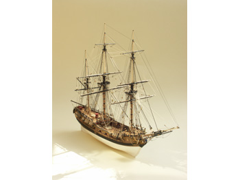
H.M.S. Fly was built at Sheerness Dockyard and launched in September 1776. She was one of the large number of Swan class ship rigged sloops designed by Sir John Williams, sleek of line and one of the last of its size to have such an ornate appearance. Admiralty orders decreed that all vessels, particularly the smaller ships were to have the minimum of decoration to save unnecessary costs. H.M.S. Fly was commissioned mainly for convoy escort and dispatch duties and few records remain showing details of her career as an operational vessel. She was nonetheless credited with the taking of two small prizes, the French privateers Le Gleneur and the cutter Trompeur. She finally foundered and was lost off Newfoundland in 1802. Swan class vessels measured 97ft 7ins on the gun deck and had a displacement of 300tons. The carried a complement of 125 and mounted 14 carriage guns (later 16) and 16 swivel guns. The Victory Models’ kit has been based on the original Admiralty plans and, at a scale of 1:64, has an overall length of 81 centimetres (just under 32 inches). The KitThe box art and the overall presentation of this kit were most impressive and showed every promise of being a real pleasure to build. An illustrated booklet describing the hull construction sequence supported the instruction manual/parts list and a further set of twelve sheets of drawings. The quality of the draughting was as good as I have seen in a kit of this class and while all text was in both Italian and English, the latter was the prime language and was concise and unambiguous. One innovation that I particularly liked was the bench-friendly size of the drawing sheets and the durable heavier weight of paper on which they were printed. All parts that had to be made from scratch, e.g., masts and spars and all pre-cut parts were drawn full size. The laser cut parts in both ply and solid walnut were finely produced and the advice to remove parts from the sheet only as required was well founded. The ornamentation was beautifully reproduced using cast and etched brass parts. Two sheets of etched brass parts were included, one at 0.25mm thickness and the other 0.50mm and provided a myriad of small parts essential for that museum quality finish. The strip wood and dowelling appeared straight and blemish free. There were three trays of fittings and where required, had been specifically produced for H.M.S. Fly. The model having been designed using the original Admiralty plans, with masts and rigging researched using contemporary sources, resulted in the provision of ten different rigging thread specifications and over 230 rigging blocks. Tools RequiredCraft Knife Adhesives, Stains and PaintsWhite PVA wood glue The above lists were taken directly from the kit manual, but I would personally recommend that a tin of etching primer be added to ensure a sound key of paint to the brass parts. |
|
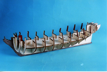
Getting StartedIt was imperative to read the instruction manuals and drawings before starting to hack away with cutting tools. It was not so much that guidance may have been required as to how to do things, but when to do them. This model in particular had several stages that needed to be done in the correct order if trouble free assembly was to be accomplished. If you bought Superglue for your last model and had some over, try it on some scrap wood before you start; old previously opened glue may well have gone off. The same goes for paints; tin lids rarely get replaced adequately to provide a good seal. You don’t want to find out on a Saturday afternoon that you need replacements just as the shops have closed! Do make sure that your tools are nice and sharp; they are essential to good results, easier and safer working. It is also a good plan to prime the sheets of etched brass parts. I use an etching primer and find that provided that the parts are cleaned thoroughly before use, the results provide an excellent key for the forthcoming paint work and minimal paint chipping back to the basic brass. The Hull ConstructionThere was an excellent pictorial guide to supplement the instruction manual for this part of the build and no problems were experienced in making the basic hull carcase. All the pre-formed parts were accurately produced and no fitting was required to assemble the bulkheads to the keel. However, sequence was important and I would repeat the manuals advice that the edges of the bulkheads and the plank termination pieces be roughly chamfered before using the glue. I also prefer to chamfer the rear faces of the keel below the bearding line to avoid very thin rear edges to the subsequent planking. The rudderpost was not therefore put on until after completion of the planking. This is a personal choice and not a criticism of the design. Once the main hull framework had been completed and all the required bulkhead edges finally chamfered to provide full-width seating for the planks, Photo 1, the main gun deck was planked on the fore and aft areas indicated in the manual, Photo 2. I used white PVA adhesive for this task and, when completed, large headed drawing pins held down the edges of the deck (planks uppermost) while the glue dried. This prevented warping and difficulty in fitting the deck to the hull. While the glue was drying, I painted the beams and the bulkhead extensions in those areas covered by the subsequent fitting of the upper deck and forecastle. (There is always some clever dick going to look at your model with a dentists’ mirror). After rubbing down and varnishing the planked deck, I used a fine scalpel to cut the deck down the centre line into two parts. This facilitated the fitting of the deck to the hull. However, it should be remembered that any adjustment required should be done by trimming the deck edge slots and not by removal of material from the centre-line edges. With the main deck glued in place, the next stage was to put the deck fittings in place, since once the upper decks are in position access is denied. These items were simple to make but a couple of points for the less experienced may be of help. The forward riding bitt assembly comprising parts 46 and 47 were best put together on the bench, the unit then dropped into the holes in the deck and Parts 57 then glued in position. The capstan main spine should be cut from 10mm diameter dowel and not 8mm as indicated in the manual. This is fairly obviously a printing error witnessed by the size of the holes in the pre-cut parts. The 22mm length suggested may need trimming down after assembly to permit the bottom face of the lower part 105 to fit flush down to the deck. Failure to achieve this state will result in the top of the capstan fouling on the underside of beam No.9a. When making the gratings, it was important to get things the right way round and note that the top faces of the battens, which run fore and aft, are to be seen in their entirety. This state is correctly shown in the hull construction manual. The assembled parts are shown in Photo 3. The upper decks were then temporarily pinned in place and their edges blended with the edges of the bulkheads to provide correct seating for the pre-formed gun-port strips. These needed about an hours soaking at the front end to make them more pliable. Even so, care was needed in introducing the bend where the weakest sections occur at the first and second gun-ports. Once their correct position had been established on the hull framework, they were securely pinned and glued in place, remembering that the ‘midships bulkhead extensions had to be removed at a later time in the construction. When the glue had dried, the stern end of each strip was trimmed up to match the contours of the stern counter patterns, Photo 4. The fore deck beam was then glued in place, being held with clips while the glue cured. This part (No.39), was a little shorter than the distance between the gun-port patterns and was be fitted centrally to leave an identical gap each side to take the bulwark planking to be done later. |
|
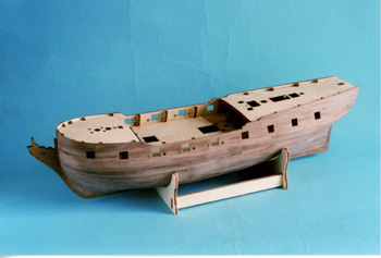
The First PlankingThe upper decks were left in place while the planking was done. The quality of the 1.5mm x 5mm lime strips was excellent and made the first planking operation fairly straightforward. Starting at the bottom edge of the gun-port strip each side, planks were laid progressively towards the keel, pinned and glued at each bulkhead position, leaving the pinheads proud for easy removal. Tapering was necessary particularly at the forward end and stealers were required at the sternpost end. Soaking of the timber was also a great help. The major point for consideration is that the planks should follow, as far as possible, their natural run and sit fully across the edges of the bulkheads. This provided a sound surface for the application of the second planking later on thus, cosmetic appearance of the first planking was not of major concern. It was important however that the ends of the planks be angled and carefully fitted against the sides of the stem and against the forward edge of the sternpost. When all glue had dried, all the pins were removed, making a double check that none had been overlooked. Sanding down the first planking with successively finer grades of abrasive paper was a task that took a couple of hours and required the wearing of a suitable mask and the frequent use of a vacuum cleaner, particularly if the work was being done in the house! The main target is to provide the base surface for the second planking, no bumps or blemishes being the order of the day. A highly finished surface was not necessary, Photo 5. The stern counter pattern was then glued in place and its edges trimmed to match flush with the first planking. The Second PlankingIn the review kit the 1mm x 4mm walnut strips came in at least two different shades and needed to be sorted before commencing the second planking. The object of the exercise was to separate those planks to be used for the area above the waterline, which were to be left natural wood (the surfaces below the waterline and the strips used for the main wales were to be painted). The manual indicated where the second planking was to start and the termination of the planking at the stern was clearly shown. Tapering of virtually all planks was required and a good soak also helped. In fact, at the commencement of planking, I used a tall vase half filled with water and put a bunch of planking strips into permanent soak with an occasional top-up. The second planking required more care than the first in order to attain the snug fitting at the ends as well as plank-to-plank. Each plank was glued in place with thick grade cyano acrylate and accurate positioning and fitting was necessary, particularly where the wood was still damp. The hull at this stage is shown in Photo 6. The rubbing down task was done as before with various grades of abrasive paper. While it was recognised that the area below the water-line was to be painted, it was still very important to get a good surface. White paint will show up every bump and blemish, in fact, I deliberately used a coat of primer to highlight any faults that could be either removed by further rubbing down or filled before painting. The temporarily fitted upper decks were now removed and eight gun carriages were glued in place. It was not forgotten that these had to be painted first. To ensure that their fitting was indeed permanent, the cast carriages were pulled across a sheet of abrasive paper to provide four small clean flats on the bottoms of the wheels. A round needle file was used to clean the grooves into which the barrel trunnions would ultimately fit before actually gluing the carriages to the deck with epoxy resin. I suspect that there will be many modellers who will be pleased with the cast carriages provided; they certainly look OK when painted. However, the purists may not be so happy and would probably prefer the task of making up wooden assemblies. The two decks were replaced using pins and glue and the hull set aside while the glue dried. |
|
Decks and BulwarksThe ears of the bulkheads were twisted off and cut flush to the level of the decks. Deck planking was finished using thick cyano, working from the centre out towards the bulwarks. The planks at that point needed shaping to conform to the plan shape of the hull. However, it is worth remembering that any small gaps will be covered by the 1mm thickness of the inner bulwark planking positioned during the next operation. At this stage, I pre-painted a couple of the 1 x 4mm walnut strips to be used to line the inner bulwarks. This enabled a sharp red line to be attained against the deck without having to scrape off any splurge of red paint from the deck later on. The results can be seen in Photo 7. Having lined the inner bulwarks, the top edges were trimmed to their correct height and made flat to correctly seat the capping rails. The mid-section capping was done with 1 x 5mm walnut strip and the pre-cut timberheads glued in place and painted black. The main mast bitts were assembled, remembering to fit the two etched brass pump brackets. It should be noted that they fit above the bitts crossbeam and not below as shown in the assembly manual. It was found useful to use the height of the pump handle support stanchions as a height gauge to correctly position the brackets. The pump handle assemblies were then made from 1mm wire, bent to shape and painted, Photo 8. Coamings to all companionways were put in place, although I decided not to add the stanchions at this stage. The mid-deck gangways were made up and glued in place. However, before doing so I suggest that the width of each pre-cut deck (31) be increased to 16mm by gluing a strip of 1mm thick scrap material along the longest edge. If you don’t do this, when you come to fit the mid-bulkhead rails (123), you will find as I did, that there is no support for the lower end of the 15mm long stanchion (214). This corrective action may not be necessary in your kit, but is worth checking before assembly. The stanchion (214) needed to be reduced on width at the top to match the width of the rail it supported. It was also painted before assembly. At this juncture I also found a shortage of ladder packs in the kit. However, Euromodels quickly rectified the situation and I understand that the matter has now been put to rights. The fitting out of the upper decks can be seen in Photo 9 and Photo 10. Headrail and Cathead AssemblyThis was arguably the most difficult part of the project. It was imperative to follow the sequence of tasks set out in the manual. However, I would add that there were one or two additional operations that made life a lot easier. Study of the drawing showed that the top outer corners of the three head timbers supported the bow head-rails and that the slots in their undersides supported the very flimsy lower bow rails. It was seen that the top outer corners needed to be angled and this was done before assembly of the head timbers. Likewise, the pre-cut slots had to be angled on their bottom faces to avoid undue strain on the very fine pre-cut lower bow rails when putting them in place. Obviously, dry fitting these items was not very practical, but an eyeball assessment of the angles minimises the hazards of filing and cutting after assembly. When this preparatory work had been done the head timbers were glued in place on the prow ensuring that they sat balanced and square. The previously prepared slots for the catheads were now opened up to final size. Parts were painted on an ‘as you go’ system for best results, either before or immediately after, assembly. The brass decorative strip, from below the cathead bracket to the after termination of the lower head rail, needed to be bent around a fairly small radius. This had to be done against the width of the section and it was found best to first file the taper on the width of the strip then do the bending before cutting the piece off to length. The longer strip definitely made it easier to bend to the shape required. The etched brass decorative pieces were then added to finish this stage of construction. I would add a word of caution at this point. Because the layout of the actual etched brass sheet had not followed the positional layout of the drawing, care had to be taken not to confuse the left hand parts with the right hand, particularly those that fitted along the edges of the bow cheeks. I found that using the decorative strip for the upper prow rail was ideal for getting the attitude of the ‘N’ pattern correct on the cheeks. The finished results can be seen in Photo 16 and Photo 20. |
|
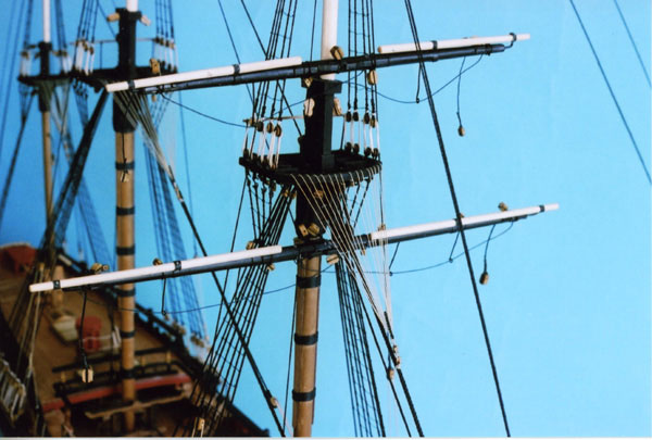
The Main Wale and Upper RailThe application of the main wale was largely a matter of getting the position right and, just as importantly, getting both sides symmetrical. Each side comprised three 1 x 4mm strips and I chose to paint the top and bottom edges before assembly, again to get a clean line with the hull. I used the decorative etched brass pieces to correctly position the upper rails and the drift rails as advised; it would be disastrous to find later when permanently fitting the decoration, that the width between the rails was too narrow! The relative positions of the wale and upper rails can be seen in Photo 8, 9 and 10. The Stern FasciaThe relevant parts of the stern fascia and glazing are shown in Photo 11. I decided that I would glaze the windows as suggested in the manual but having had bad experiences in the past where glazing suddenly decides to ‘ping’ off the back of the frames, I took a further preventative precaution. Having glazed each window as directed, I took a strip of black card that had been cut to match the height of the windows and placed it behind the glazing, sticking it to the back of the fascia between the windows. This was not readily apparent from the outside and even if the glazed pieces should ever become loose, they were totally constrained by the card. Be careful of using cyano on joints involving clear acetate sheet, it can cause fogging and looks pretty awful. Generally speaking, PVA is less hazardous. All remaining decorative strips were then put in place together with the figurehead and other castings, all benefiting from pre-painting. Channels, Gun-Ports and Chain-platesWhether the port lids were to be assembled in the open or closed position, I suggest that they be dealt with before putting the channels in place. The hinges and eyelet were assembled to the lids on the bench. I chose to put mine in the closed position and used the projecting hinge stubs as a guide to depth when gluing them in place. A 0.75mm hole was drilled centrally just above the top edge of each lid and the port lifting tackle rigged. Each channel was identified for port and starboard location and the eyelets fitted accordingly. The fit of each channel with the side of the hull was checked for total seating and pins placed into the rear edge. The deadeyes and strops may be assembled before or after fitting the channels to the hull. I prefer to do the task on the bench, but that is a personal choice to avoid unnecessarily stressing the channel/hull joint. The chain-plates are fiddly and laborious although made to conform to the original design and are easier to fit than many I have found in the past. Even so, for those of us with thicker fingers, I found it easiest to put the top two links together, hang them on to the eye at the bottom of the deadeye strop then, use a needle in the hole at the bottom of the lower link to guide them into alignment and mark the hull for drilling. The top hole of the lower plate is then pinned through the upper links into the hull. A needle is again used to align the bottom plate and mark the hull ready for drilling for the final pin. Again, this is a personal choice of working but I recommend giving it a try if you experience difficulties. At this stage of the proceedings, I would suggest that a check be made to ensure that the swivel gun posts have been drilled. It would become increasingly hazardous to do the drilling once the masts have been stepped and the rigging started. The completed hull made a very acceptable model in its own right and would be suitable for anyone with a small display area, Photo 12. Deck FittingsSkylight, belfry, tiller assembly, etc. were made up put in place. The pin racks at the stern were pinned and glued to the inside edge of the upper aft capping rails to provide a strong joint. A further check was made to ensure that all eyelets and cleats had been positioned on deck before proceeding with the rigging of the tiller and ships wheel, all being things that would get more difficult as the build progressed. I mentioned the eyelets in the previous paragraph and further, I would recommend that the forthcoming rigging drawings be studied to identify those of them that should have blocks attached. Again, it is a job that is better done sooner than later. The BowspritThe bowsprit has two tapers. They appear to merge at a point about 80mm from the butt end and run from 8mm diameter at that point to 7mm diameter at either end. The forward end had to be provided with a 4mm diameter spigot for fitting the cap Part 50. I used a piece of scrap 5mm walnut to make a new cap with two holes drilled at 20 degrees set at 7.5mm apart, rather than trying to adapt the cap provided. All cleats were made as described in the manual, the glue being left to thoroughly dry before attempting any tapering of their top faces, Photo 13. The assembled bowsprit was painted black at the doubling before blocks, eyelets and deadeyes were added. Lower MastsThe manual and drawings gave a fairly clear indication of how the various components should be prepared and put together. One procedure I adopted for making the masts from kit parts was to build the tops, trestletrees and crosstrees first. This provided an accurate dimension for making the square sections at the top of the lower masts and the bottom end of the topmasts. Eyelets were fitted to the tops as indicated. It was essential to make sure that these were well fitted and secured. The last thing you would want to happen is for one to pull out during the rigging process, because getting it back would be almost impossible. The eyelets, wooldings and masthead bindings are shown in Photo 14. When assembling the various mast parts, it was essential to observe the correct sequence. Everything was dry fitted first but noting that the tops had to be put in place on the lower masts before adding the simulated iron straps to the lower masthead. TopmastsOne minor problem that had to be overcome was the square sectioned portion at the bottom of each topmast. I found that the reduced section of 5mm square on the foremast needed to be taken down to 4mm and extended to the bottom, then the lower 10.9mm built up with 1.0 x 4mm scrap to provide the 6mm square section required. A similar rectification is required for the main and mizzen topmasts. On the latter, the mast cap should be slid down the topmast before fixing the truck at the top. Topgallant MastsThe construction of the topgallant masts was done in a similar manner to the topmasts. However, it must be remembered to slip the topmast cap into position before gluing the truck in place at the top of the pole. Mast AssemblySequence was all-important and a dry run helpful to ensure that I didn’t finish up with something I couldn’t get on! Blocks were identified and attached where indicated. The holes in the blocks were also checked out, first to make sure they were there and secondly to ensure that they were clear. The one that the thread will not go through is always the one in the most inaccessible position! The deadeye strops either side of the tops were fitted with deadeyes and placed in position. It may seem a bit ‘belt and braces’ bearing in mind the self-locking design of the strops, but it is worth applying a small dab of adhesive to the slot in the top. Strops are features that you definitely don’t want to come loose during the rigging process. The YardsThese were all straightforward to make following the dimensions provided on the drawings. Small flats were filed on the spars to provide a good seat for the various cleats made from 1mm square or 1 x 2mm strip. These were stuck on to the yards well oversize and cut to length and tapered after the glue had thoroughly dried. I was disappointed in the provision of copper strip for making the stuns’l boom irons and substituted black cartridge paper which made a better and neater job all round. 1mm diameter wire was used for the ‘iron’ bracket at the end of the yard. The iron fitted into holes in the yard and the boom. Once the correct 45 degree attitude was established, I drilled through both yard and spar toward the butt end of the boom and passed a pin through to secure. Blocks and footropes were added as required and the finished yards put to one side. Note that all brace pendants were tied to aft on the yards except those for the mizzen crossjack yard, which were tied forward. A double check was made to identify those blocks that needed an eye for attaching tackle falls. Stepping the MastsThis may be done as indicated in the manual, that is after securing the yards to the masts or, as I chose to do, before putting the yards in place. This is a personal choice, having advantages and disadvantages. I prefer not to have the yards in the way when tying on ratlines later in the rigging process, but then suffer the possible fiddling about with trusses and parrals when I finally come to put the yards on. You pays your money and you takes your choice, so to speak. The bowsprit was stepped first paying attention to alignment with the centre of the hull and then getting the cap perpendicular with the stem. The gammoning was then put in place. Note that the gammoning was not just a matter of wrapping a length of rope ‘twixt bowsprit and stem several times. It was passed from the aftermost position on top of the bowsprit to the most forward position in the slot through the stem. This induced a twisted effect prior to tying on the frapping turns. Once the gammoning is correctly applied the effect is hardly noticeable except, that is, to the eye of a discerning judge. Medals and certificates at exhibitions can be won or lost by such detail. Having checked that the three masts had been completely ‘blocked’ and ‘deadeyed,’ they were dropped into position, not forgetting to slip the mast feet in place first, Photo 15. Standing RiggingOne of the biggest problems with rigging is how much there is of it. Most kits suggest a sequence of application in the manual that offers a sound approach to the task and one that will provide the least difficulty. This kit was no exception. The rigging was not quite as complex as it first appeared; it was the amount that caused the illusion, which is why the sequence of tying it all on was so important. If you feel that you wish to deviate from the suggested path, for whatever reason, on any period ship rigging project, then one simple rule is worth remembering. Always maximise the amount of hand and finger room left for the following stages; that space gets smaller and smaller as the rigging progresses towards completion. As always, removal of rings and watches is important. Working from the deck upwards and from the centre-line outwards is a good basic rule to bear in mind. Knots are better sealed with dilute PVA adhesive rather than cyano. The standing rigging is, for the most part, all your black thread work and represents the rigging that holds everything up and stable. The sequence of application was particularly important and that described in the manual worked well, although I felt that information on some features was a bit sparse, the rigging of the truss pendants to the foreyard and main yard for example. When tying on ratlines, I use a sheet of plain paper behind the shrouds and between the deck and the underside of the top. This is to ‘isolate’ the shrouds from other details and help focus the eyes without too much strain. Even so, it is always a good idea to tie say, one flight at a time and then do something else for a while before continuing. I deviated from the sequence in one respect; I chose to leave rigging the back stays until much later in the rigging process. This was a personal choice and one adopted purely to leave a bit more room to get hands and fingers into the centre areas of the model when applying the running rigging later on. The standing rigging to the bowsprit, fore and main masts is shown in Photos 16, 17 and 18. It should be noted that the shifting backstays are basically the same on both foremast and mainmast – they both run down from the crosstrees at the head of the topmast. I mention this only because the drawing shows the stay running down only from the top at the head of the fore lower mast. Note also that the picture on the box lid is suspected of being printed from the wrong side of the transparency. The main stay should pass the foremast to starboard and not port as shown. Follow the drawings for the correct rigging. Running RiggingFor a kit of this scale there is a heck of a lot of running rigging and I would suggest that, from the outset, you identify the various sizes of thread. This was done by comparison, since the several reels and hanks were not marked with the relevant sizes. The foremast was fitted with its three yards and these were rigged first followed by those on the main and mizzen masts. The bowsprit was left until last mainly because the yards were a bit vulnerable when repeatedly turning the model round from port to starboard. I preferred to use diluted PVA to seal off all knots. Cyano has its uses however, and is fine for stiffening the ends of the various lengths of thread to form a sort of built –in bodkin. For best threading through blocks, trim the stiffened ends of the thread on an angle to form a point. The sequence indicated by following the drawings worked well, but again, I would stress the need to study the drawing long and hard before you start. Being familiar with the run of each line from spar to belaying point is essential. It was also helpful to gently tension each piece of rigging before tying off at the belaying point to ensure that there was no interference with other lines on its passage down to deck. ConclusionsThis kit makes up into an attractive, highly detailed and decorative model, in fact a real gem. It is not really one for the beginner and certainly some knowledge of rigging, or reference to the subject, would be to advantage. Given that, the result can be very impressive and I can see it turning up in competitions and exhibitions for a long time to come. I thoroughly enjoyed building this kit and I have to say that it offered a standard that bodes well for the forthcoming kit for H.M.S. Vanguard that is expected soon. The materials were of good quality and all fittings and castings crisp and clean. With a fairly small workbench, I found the smaller format drawings an advantage. The resulting half working scale was not found to be a problem since all finer detailed stuff was drawn full size. If I had a wish list, right at the top would be a request that where black rigging is specified, black thread is provided, rather than an instruction to colour tan thread with Indian ink! Second on my list would be that an alternative way to do the stuns’l boom irons be found and, finally, clarification and perhaps further detail to some of the rigging features. Truss pendants and deck blocks specifically come to mind. You really can’t go wrong for the price; there are many enjoyable hours to get out of this particular box and the results can be most rewarding. H.M.S. Fly (EVM 1300/03) costs £235.00 and is distributed and retailed by Euromodels, Woodgreen Farm, Bulley, Churcham, Gloucester, GL2 8BJ. Tel: 01452 790800 Fax: 01452 790880 E-mail [email protected] or visit their website www.euromodels.co.uk. |
Want the latest issue of Model Boats? Use our magazine locator link to find your nearest stockist!
 Make sure you never miss out on the latest news, product reviews and competitions with our free RSS feed

We welcome well written contributions from Website members on almost any aspect of Model Boating with a particular emphasis on practical hints, tips, experience and builds.
In order to maintain a consistent standard and format, all suggestions should first be sent to me by Personal Message for approval in principle. Only a very limited amount of time is available for editing contributions into a suitable format for placing on the website so it is important that the material is well presented, lucid and free from obvious spelling errors. I think it goes without saying that contributions should be illustrated by appropriate photos. I shall be happy to give advice on this.
The Member Contribution area offers space for short informative mini articles which would not normally find a place in Model Boats magazine. It is an opportunity for Website Members to freely share their expertise and experience but I am afraid that virtue is its own reward as there is no budget to offer more material recompense!
I look forward to receiving your suggestions.
Colin Bishop - Website Editor
Model Boats Magazine
- Landing Craft Mini PLan
- Riva Aquarama Build
- Scale Colour, Sound & Speed
Digital Editions
- Access your digital editions
Subscribe Now
- Every issue delivered right to your door
Renew Now
- Save & never miss an issue!










 Register
 Log-in


