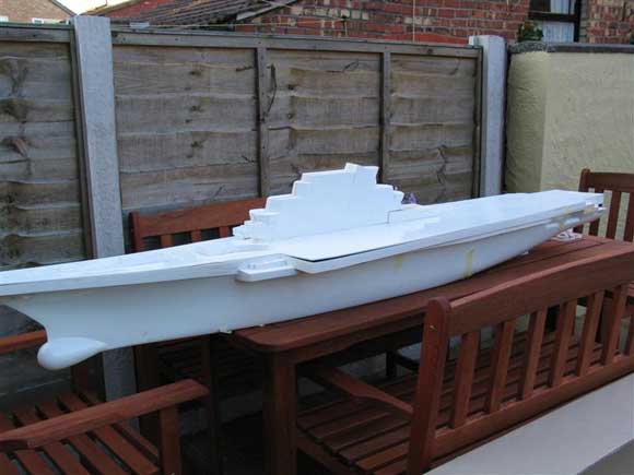
Welcome once again to our regular sortie into the world of fighting ships. This month sees the start of an extended series on the building of the Soviet aviation cruiser Kiev. Pic 1: The GRP hull, deck and superstructure, which formed the bulk of the Kiev Kit at 1:144 scale. Pic 2: Kiev at anchor. Pic 3: The graceful lines of the Kiev. Note the unusual stern. Pic 4: Helix Ka 27, like the Kiev’s Hormone KA 25s uses contra-rotating rotors. Pic 5: Kiev’s radars from left to right ‘Top Steer’, ‘Top Sail’ and the forward “HEAD,’ LIGHT’ pair. The white-coated radar domes are part of the ECM outfit and are still termed ‘Side Globe’ in NATO nomenclature even though the Russian names have been available for many years. The radar array mounted atop of the Bridge is referred to ‘Owl Screech’. Pic 6: Modellers draughts of Russian origin and used as reference.The building of the Soviet Aviation Cruiser Kiev, Part One.For many years I’ve held an ambition to build a large model of the Soviet Carrier (correct terminology - Aviation Cruiser) Kiev and this ambition was thwarted because of a critical lack of good photo references and plans of Kiev. However seven years ago I was fortunate to acquire a reasonable set of modeller’s draughts from Russia, but once again the project was delayed because of more pressing commitments and the plain fact that a hull to a scale of 1:100 was going to be over 2.5m in length, thus a re-think was the order of the day. You may ask ‘why the Kiev?’ Well I think many modellers do have a project that they have a passion for and some never realise that passion, but others do. For me it was Kiev and a 20-year wait. On a visit to the Dortmund model show in 2004, I was in the right place at the right time. There were a number of friends at Dortmund that know of my passion for this ship and when I was told by Dave Abbott that a 1:144 kit of Kiev was available on one of the many traders stalls I just couldn’t contain my enthusiasm. Here at last was a model of the right size and in kit form. |
|
The kit manufactured in the Ukraine was, without being unkind, disappointing. The drawings were less than adequate and there were no instructions of any kind. However I convinced myself that these were minor problems, until I saw the hull, deck and superstructure, which were all moulded in GRP. The hull although well made was in a number of respects deficient in shape. The deck was far to heavy with the shape of the superstructure also open to question. The kit was made as a static model hence the moulded GRP deck. Many of the fittings were also open to interpretation. On the other hand, the scale was perfect and to be fair my enthusiasm remained undiminished and perhaps even clouded my better judgement, Photo 1. Eventually I returned to the UK with one large box and a few Euros less in my pocket, but once again circumstances intervened and it wasn’t until the winter of 2006, two years later, before a start was made. Kiev ‘Takticheskoye Avianosny Kreyser’ - Tactical Aircraft carrying Cruiser. Before we continue with the construction of the model a few notes explaining the purpose of this once very powerful warship. Kiev was a concept conceived by the Soviets in the 1960’s, not as a carrier in the classic sense, but in essence an ASW (anti-submarine warfare) platform like the previous Moskva class. The purpose was the same, but with Kiev this included a squadron of 12 Yak 38 Forger VTOL fighter aircraft plus 19 Hormone ASW helicopters and 2 Hormone B SSM targeting helicopters. There are a number of task similarities between Moskva and Kiev, but the two ships possessed major differences in appearance, performance and armament. Kiev was laid down on the 12th July 1970 as project 1143 at the Nikolaev shipyard close to the Black Sea port of Odessa. Entering service on 28th of December 1975, Photos 2 and 3. Kiev had a displacement of around 41000 tons full load on a hull 273m long by 49.2m across the flight deck. According to Pavlov in his book, Warships of the USSR and Russia, 1945 - 1995, the Kiev design began with a displacement of a mere 15000 tons, progressively being revised as additional elements were added. For example and unlike that of USN and RN carriers of the period, the defensive/offensive armament of the ship was comprehensive. To accommodate these additional weapons the entire forecastle was given over to supporting the various systems. Mounted in massive tube like elevating launchers were the principle anti-ship missile system, the SS-N-12. Further forward are the RBU6000 launchers, a horseshoe shaped ASW rocket mortar system. |
|
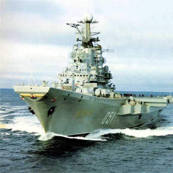
Air DefenceAir defence was provided by a combination of the longer range 55km SA-N-3 Goblet (NATO code) launcher just forward of the superstructure and two retractable SA-N-4 Gecko to provide short-range (15km) point defence (similar in purpose to the Sea Cat system deployed on RN ships of the period, but operationally different). The second of the two retractable launchers was located on the starboard side immediately adjacent to the after 76.2mm/60. Also located forward on a raised deck housing was the forward 76.2mm twin naval gun and forward of that the SUW-N-1 launcher for the FRAS –1 (Free Rocket Anti Submarine). This was a weapons system of last resort, as it was a short range ballistic nuclear weapon, unguided and with a limited range of 30km could be seen as a weapon that there would be some reluctance to make use of! Air GroupLike the RN Invincible class, the Kiev’s operated the YAK 38, a VTOL aircraft but unlike the Harrier this used a combination of two dedicated forward lift engines and a single dual lift cruise engine. This configuration was to provide a greater lifting capacity, but failed in a number respects to live up to expectations. Scratch building these to 1:144 scale will be discussed later in the series. Kiev also operated a combination of two types of helicopters. The Hormone B for targeting and the Hormone A for ASW. Unlike helicopters in NATO navies, Soviet carriers like Kiev used the Hormone and the later Ka 27 Helix, with a system of contra-rotating rotors, Photo 4. For bringing aircraft from the hanger spaces below there were two elevators. One adjacent to the superstructure amidships, another sited abaft of the after 76.2mm gun and also a much smaller elevator for accommodating deck vehicles and ordinance. Certainly peculiar to Soviet /Russian warships is the extensive use of a narrow gauge track, which is sited along the deck both fore and aft for the movement of ordinance and other equipment. RadarsUnlike the present generation of radar arrays, where reduced radar cross section and phased array determine that these radars form an integral part of the superstructures, those used on Soviet warships during the Cold War were the very antithesis of the new generation of modern radars in their construction. An example of which is the huge ‘Top Sail’ long-range 3D Air Search early warning radar and the ‘Top Knot’ spherical navigation radar. As we progress through the construction of the model, many of these features will be highlighted and explained, Photo 5. Kiev - the ModelAs mentioned in the preamble, the kit was bought in Germany and was of Ukrainian manufacture. Also mentioned were a number of deficiencies in the shape of the hull form forward. However having a modeller’s drawing of Kiev was the catalyst that allowed the kit to be built. This drawing can be seen in Photo 6. After assessing where the hull needed to be altered, work on the model could begin. Essentially the two most noticeable features that required attention were the shape of the forward upper knuckle and the shape of the angled deck. Both of these features can be identified in this superb photo of Kiev towards the end of her life as an operational carrier, Photo 7. Note the shape of the upper knuckle and the fact that on the model this was to exaggerated in depth and needed to be reduced and given a sweep that conformed to the drawings. |
|
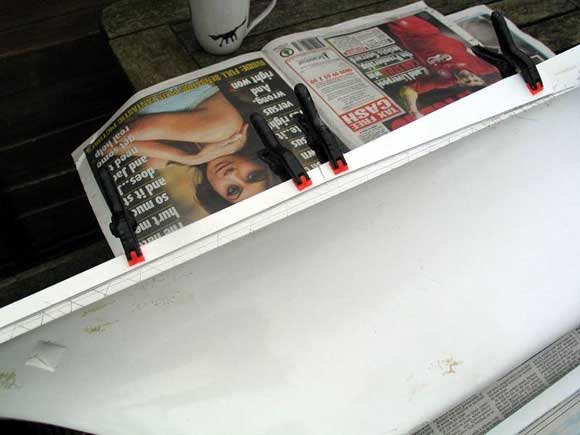
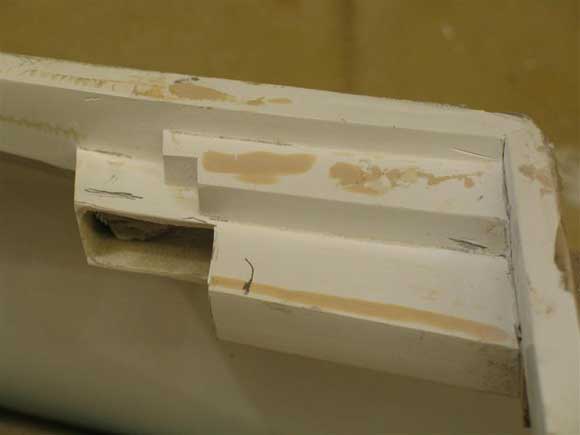
Altering the Bow KnuckleAlterations to this part of the hull involved the amended shape to be lifted from the drawing and transferred to a plastic profile, which was put in place against the existing bow section, Photo 8. A line was scribed, the former removed and a cutting wheel was used along the line as in Photos 9 and 10. In order to maintain the sweep of the hull upward a section of the hull approximately 25mm diminishing to 10 mm was cut and removed, leaving a section of hull as in Photo 11. Note that to maintain the integrity of the hull forward only one side was removed at a time. The gap was covered internally with zinc mesh, the sort of material readily available in car accessory outlets. Followed both externally and internally by fillers and generally rubbed down to conform to the sweep of the hull up to the re-aligned knuckle, Photo 12. With the final result conforming reasonably well with the drawing and that seen on the full size vessel, Photo 13. Amending the Angled Flight Deck.Kiev possessed an angled deck of five degrees to port from the centre line. This feature was fitted to create more deck space and had no relationship to take offs or landings as on USN carriers. The angled sponson supporting the deck was moulded as part of the hull. However it would appear that during the curing process this sponson pulled downwards and would have been impossible to lift up to give a straight line athwart ships and marry with the deck. The only answer was to separate part of the sponson from beneath and along the forward edge, thus releasing the tendency for this part of the moulded hull to slope downwards, Photo 14. This simple expedient allowed the sponson the freedom to move upwards and regain its level athwartships. Zinc mesh and fillers were added to reinforce and bond together the separated sections of the sponson, Photo 15 and 16. Note the lip along the deck edge. This would eventually provide a good seating for the deck without the need to add any additional deck edge stringers. Amending the 30mm AK630 CIWS PlatformAs mentioned above it became necessary to separate the angled sponson from the forward 30mm gun platform. However this platform, which was also part of the moulded hull form, was of the wrong shape, refer back to Photo 1. The shape was lifted from the drawing and the alterations took the form of removing part of this sponson creating an ‘L’ shaped section as in Photo 17 and reinstated as per the shape seen on Kiev, Photo 7. The material used in reshaping this platform consisted of 1mm ply for the lower sections and 20thou. styrene sheet for the upper part, Photos 18 and 19. Amending the lower sponsonThe lower sponson, which adds structurally to supporting the angle deck, needed to be re-shaped to give the correct depth. Although this part of the hull was in fact moulded in the generally correct shape, the angle of slope and depth did not conform to the drawing or the photos. The first task was to alter the initial shape by lifting the sponson 15mm clear of the existing moulding. This involved laying out and bonding into place a timber strip, Photos 20 and 21. A further strip of 1mm ply was sited as per the depth required, beneath the existing lower sponson, Photo 22. Here the sloping section could be fitted into place as in Photo 23, extending to the entire length, Photo 24. Note that to conform to the curve of the side of the hull the length was divided into 5 segments. The completed results conform to the plan even down to the sharp slope upwards into the lower part of the 30mm CIWS platforms. With the depth of the lower sponson increased, the existing opening into sides of the hull was almost covered. Thus a new opening needed to be provided for which conformed more accurately to the drawing and original pictures, Photo 25. DeckingOriginally the GRP deck was to be self-supporting. However as this deck was discarded in favour of a marine ply, the inside of the hull at deck level needed to be braced to support the timber deck and provide strength and rigidity. The timber of choice for the bearers was ramin using a combination of 15mm x 6mm for the athwartships bearers whilst lengths of 8mm square were used for longitudinal bracings. A space was left clear amidships to allow for the deck opening bearers, which were added later once the size of that opening was determined, Photo 26. When building a hull from scratch or if using a GRP hull, I prefer to have the deck inside and flush with the top of the hull, but with the Kiev hull this was not possible. Thus the deck had to fit on top of the hull as shown in Photo 27. Once marked and cut to size the sections of the deck were temporally secured to the hull with masking tape (the majority of the deck sections were to remain temporary, until ballasting and sea trials were completed), Photo 28. The next task was to remove a section of deck that would provide access into the hull for batteries etc. When building carriers with expanses of uninterrupted deck space the problem faced is to make that all-important opening as unnoticeable as possible, which is often quite difficult . Personally when providing for opening on warship models such as destroyers, cruisers, etc., the aim is to minimise, if not eliminate any obvious cuts along the deck and use the edge of the superstructure to define the size of the opening . With warships having superstructures within the centre of the deck area, achieving this aim is less problematic, but with carriers another approach is necessary to achieve the same results. When building Moskva the entire flight deck was a single piece of styrene, which in retrospect was an unwise choice, as styrene in large unbroken areas has a tendency to warp, whereas timber is more stable, but requires greater effort to achieve a good painted surface. That leaves aside the fact that Kiev had heat resistant tiles 50cm Square laid across 50% of the deck space, a feature for the model that remains to date unresolved . To give the maximum access with the minimum of visible cuts into the deck as discussed earlier, it was decided to follow a line that corresponds with the separation of the angle deck and parking area, a division emphasized by two parallel white lines running fore and aft on the angled flight deck, this can be seen clearly in Photo 29. The positions of the flight deck, and main elevator were worked out using a combination of drawings and photos. The results can be seen in Photos 30 and 31. The island superstructure will eventually sit on the area of deck forming the hatch. The deck access hatch now follows the lines of the parallel white deck markings and the forward SA-N-3 deck-housing and hides the athwartships cut, Photo 32. Once removed the hatch is reinforced with cross bracing timbers of ramin and made to fit snugly into place with almost no gap, Photo 33. That’s it for this month. Next time, I shall continue with the fitting of the running gear, ‘A’ frames, making the rudders and supports, the installation of the motors, speed controllers, rudder servo, linkages, plus the selection of the right batteries to provide power and ballast. |
|
Acronyms , getting it wrong and getting it right!The magazine editor recently received a letter from John Haynes regarding an incorrect reference made in issue No.680 concerning the STAAG mounting as fitted to the Type 61 Frigate HMS Llandaff . These shortened acronyms are useful and are universally accepted as an easy way of describing a particular mounting, piece of equipment or a weapons fit. However if incorrect they can be misleading and as we shall see I don’t always get them right. But in this case I like to think this was a typing error, but that’s my excuse! John Haynes goes on to write: ‘Dear Editor, regarding Dave Wooley's article, on page 26, the first word from the acronym STAAG is ‘Stabilised’ not ‘Standard’, which was of course the whole point of the mounting. It was said at the time (1950), although I don't know whether it was so, that in the ideal conditions of range firing at an aircraft towed drogue, the guns would follow along the tow line after destroying the drogue, threatening the TT aircraft! The Mounting was no good on shipboard: it could not cope with ship vibrations’. Thanks John for correcting the slight but misleading reference. Answer to last months Mystery Picture is the USS Carronade For many Readers from the UK this particular type of ship may well have been a mystery, as only one of its kind was built post WWII. The photo of Carronade was from the photo archive of Nobie Smith, via Bill Clarke and is a particularly rare picture. Carronade could be seen as a throw back to the LCT(R) or landing Craft Tank (rocket] used in large numbers during WW2 for the bombardment of hostile beaches before any beach landing. As can be seen in last month’s mystery picture, Carronade had a number of similarities to the wartime LCT(R) with all 8 rocket launchers mounted forward, but carried a 5inch /38 calibre gun forward of the superstructure. Carronade was built as a dedicated fire support ship (LFR) at Puget Sound and entered service in May of 1953. This 1500 ton, 245ft long vessel had unlike the LCT(R) no other secondary function and it could be said that its design was inspired by the Korean conflict and the Inchon landings in particular. Although decommissioned in 1960, Carronade was brought back into service in 1965, just as the Vietnam war was entering a critical phase, but was withdrawn from active service in 1973 as the war in South East Asia was drawing to a close. Although the need for such a vessel was questioned, the new trend emerging is for land attack vessels and in these there is some commonality to the Carronade. However direct beach landing of the type for which the Carronade was designed, will perhaps be more part of history than the future of amphibious warfare. Last months ‘What type of ship are we looking at? Answer: It is RMAS Goldeneye. RMAS Goldeneye was operated by the Royal Maritime Auxiliary Service and was classed as a mooring and salvage vessel. Built by Brook Marine and forming part of the Wild Duck Class, Goldeneye with a full load displacement of 1076 tons entered service with the pennant number P195 on 21 December 1966. Initially forming part of a six-ship class all with the prefix ‘P’. However the last two to be constructed at Robb Caledon Ltd, Goosander and Pochard, were later issued with the pennant numbers A164 and A165 respectively. The design of the Wild Duck class in the early 1960s was prompted by the need to combine a number of tasks, usually undertaken by dedicated vessels into that of a single hull. These tasks included, laying out and servicing the heaviest moorings used by the fleet, booms for harbour defence, heavy lift capability for salvage work and facilities for divers. The remainder of the class were Mandarin (P192), Pigtail (P193) and Garganey (P194). Goldeneye was sold out of service into the commercial Sector during 1991, with the duties and tasks of the Wild Duck class now being undertaken by the two ships of the Sal Class, Salmoor(A185) and Salmaid(A187). This Month’s Mystery Picture (Pic 34)The clue is, look to the funnel and what was so unusual about this vessel? References and AcknowledgementsKiev ref: Guide to the Soviet Navy Fourth Edition pages 164-167, Soviet Warships by John Jordan pages 77-98. Warships of the Soviet Navy, pages 40-41. |
Want the latest issue of Model Boats? Use our magazine locator link to find your nearest stockist!
 Make sure you never miss out on the latest news, product reviews and competitions with our free RSS feed

We welcome well written contributions from Website members on almost any aspect of Model Boating with a particular emphasis on practical hints, tips, experience and builds.
In order to maintain a consistent standard and format, all suggestions should first be sent to me by Personal Message for approval in principle. Only a very limited amount of time is available for editing contributions into a suitable format for placing on the website so it is important that the material is well presented, lucid and free from obvious spelling errors. I think it goes without saying that contributions should be illustrated by appropriate photos. I shall be happy to give advice on this.
The Member Contribution area offers space for short informative mini articles which would not normally find a place in Model Boats magazine. It is an opportunity for Website Members to freely share their expertise and experience but I am afraid that virtue is its own reward as there is no budget to offer more material recompense!
I look forward to receiving your suggestions.
Colin Bishop - Website Editor
Model Boats Magazine
- Landing Craft Mini PLan
- Riva Aquarama Build
- Scale Colour, Sound & Speed
Digital Editions
- Access your digital editions
Subscribe Now
- Every issue delivered right to your door
Renew Now
- Save & never miss an issue!





 Register
 Log-in


